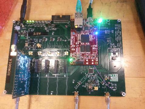
The dDOS (digital diffuse optical spectroscopy) Spectrum Analysis Unit (dSAU) is a device being developed for Professor Darren Roblyer and the Biomedical Optical Technologies Lab (BOTLAB). It will aid in his research in the use of diffuse optical spectroscopic imaging for monitoring the effects of chemotherapy on cancer cells. The device must be able to simultaneously create six frequency sweeps that will modulate external laser drivers through user specified frequency ranges between 50 MHz and 400 MHz. Secondly, the dSAU must also be able to measure two waveforms, one from the aforementioned output and the other received from an external amplified photodiode that will measure the light scattered off the tissue from the modulated laser at a point. Furthermore, the Analyzer must communicate this waveform information to a PC running custom software for recording and visualizing the data. This software must also be able to set frequency sweeps and otherwise control the Analyzer. In order to meet these goals we designed custom printed circuit board(s) with six direct digital synthesizer chips for producing the output waveforms, a two channel 14 bit 250MSPS ADC for measuring the inputs and a Zynq SOC (ARM + Artix-7) with custom firmware and running Linux for controlling these devices and communicating with the PC. We also developed custom PC software written in Visual C++ 2010 and designed to work on Windows 7. All communications use 1000Mbps Ethernet over copper and are platform agnostic.
This project was carried out as a part of an ECE Senior Design Project for the class of 2014.
SVN Repository for this project https://ohm.bu.edu/svn/DOSI/
Dean De Carli's guide for working with this project: https://docs.google.com/document/d/1Gha0St-Lx_YFLsQZqxXW77Mn6YFX3hr4UHIMxnKWbDc/edit?usp=sharing
SD-card Images
Useful bits of information
- Bad bits in the ADC stream can be fixed by adjusting the clock edges in register 0x44 of the ADC. The current working value is 0xb4
Lab Notebook
TODO List (summer 2015)
- Add value checks for parameters on the server side
- Add check that we will not exceed allotted memory in RAM (I believe it is a max size of 256 MB)
- Give each DDS it's own setting for the ramp parameters
- Give each DDS it's own amplitude setting
- Basically, vectorize all settings
- Allow phase and amplitude ramps
- Will require a little extra work. Currently, the parameters for the ramp limit and ramp step size are given in MHz, and then converted into a frequency word before being passed to the DDS. This frequency word conversion does not work with phase and amplitude. Consult DDS data sheet for more information.
- Time stamps of sweeps
- Synchronize the start of a collection with the start of a sweep
- Long term goals:
- Increase max sweep size, preferably continuous stream of data from ADC->PL->Processor
- Asymmetric mutli-processing?
- Store Data directly into DDR3 memory?
- Ping-pong DMA buffers?
- Perform FFT on board and stream real-time spectral data to computer
- Increase max sweep size, preferably continuous stream of data from ADC->PL->Processor
TODO List (from 5/14, depreciated)
- Add SVN Checkout instructions
- Add linux console details (baud rate, device etc)
- Corrected BOM for DDS (xls and csv) w/ designators (Chris)
- Updated Altium/Gerber?/PDFs for PCBs (all changes implemented)
- Assembly drawing for:
- DDS (Tom)
- Motherboards (Chris)
- microZed setup instructions (Chris)
- Set up SVN repository (Dan)
- Populate SVN repository (CHris)
- Document Protocol as implemented (not as specified) (Chris)
- Instructions on setting up software
- Local copies of all libraries
Revision A
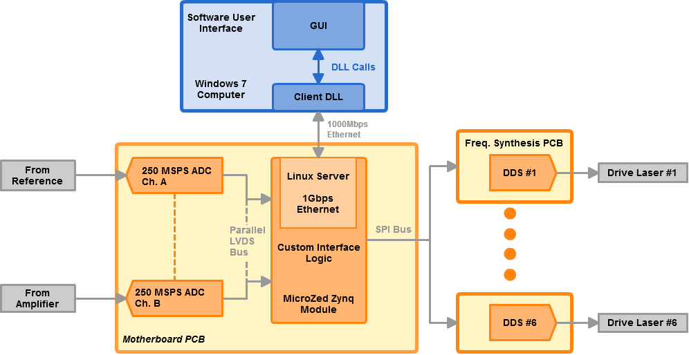
Above is a block diagram of Revision A Analyzer as implemented and finished in May 2014. From organizational standpoint our team was divided into three major groups: hardware development, software development and firmware development. This is important to note throughout the report. While the boundaries of the hardware team are pretty clear the firmware and software groups do have a much fuzzier boundary. We will define firmware as any binary, FPGA bitstream, or related work, which runs on, or configures, the MicroZed?. The software on the other hand will be anything which runs on the computer. The distinction here is that the firmware, can be changed, but shouldn’t (thus the term "firm") and the software is simply an interface for talking for our final hardware solution and could be re-implemented without needing to redesign the hardware.
Our development environments are varied, but can be summarized as following:
- Hardware: Altium Summer 2009 through a BU license. Further details are discussed in the Hardware Report.pdf
- Software: Visual Studio 2010 using Visual C++, compatible with Visual Studio Express C++, further described in the Software Report.pdf
- Firmware: Xilinx Vivado 14.3 and Xilinx ARM GCC cross-compiler, which is descrhttps://edf.bu.edu/svn/edfibed in the Firmware Report.pdf
Specifications
| Parameter | Specification |
| Frequency Synthesis Frequency Range | 0-400 MHz |
| Maximum Number of Daughterboards | 6 |
| DDS Input Clock | 25 MHz (external clock support included) |
| Number of ADC Channels | 2 |
| ADC Bits | 14 2's Complement Signed |
| ADC Sampling Rate | 250 MSPS (external clock support included) |
| Noise Floor (Full Scale Referenced) | -100 dB |
| Motherboard Average Operating Current | 0.885 A @ 5 V |
| Freq. Synth Daughterboard Average Operating Current | 0.3 A @ 5 V |
| ADC Input Impedance | 50 Ohms |
| FPGA to ARM CDMA Throughput | 3 Gbps |
| Ethernet Transmission Throughput | 170 Mbps |
| Firmware Swep Throughput | 1 Gbps |
| Motherboard Dimensions | 9.475" x 6.4" |
| Freq. Synth. Daughterboard Dimensions | 2.5" x 3" |
| Full Assembly Dimensions (no box or standoffs) | 9.475" x 6.4" x 2.6" |
Quick Start Guide
Jumper Settings
Starting a Measurement
Power Off Procedure
Getting the project for development
Hardware
Motherboard
- Altium Project (zip)
- PDF Booklet (pdf)
- PCB (gerbers, pdfs)
- Bill of Materials (xls)
- Important Datasheets
- Engineering Change Orders
Frequency Synthesis Board (Revision 2)
- Altium Project (.ZIP)
- PDF Schematic (.PDF)
- PCB Gerber & Drill Files (.ZIP)
- Bill of Materials (.CSV)
- Important Datasheets
- Engineering Change Orders
- Pick & Place Files (.CSV), (.TXT)
Frequency Synthesis Board (As Built)
- Altium Project (zip)
- PDF Booklet (pdf)
- PCB (gerbers, pdfs)
- Bill of Materials (pdf) (.csv) (.xlsx)
- Important Datasheets
- Engineering Change Orders
Firmware and Linux
FPGA Development
Development Environment
Install Vivado 2013.4. Make sure you include the SDK because then it will automatically install the appropriate GCC cross-compiler for you. Once you have downloaded Vivado you simply need to run the installation script to finish the installation procedure.
Once this is done you can cross-compile code to run under Linux and the ARM core, and also .bit files to program the FPGA portion of the Zynq (essentially an Artix-7).
Linux Configuration
If a new device tree is created then the Ethernet configuration must be copied in manual from the sample xilinx.dts file into the new xilinx.dts file. More information can be found in the "Firmware Report.pdf"(pdf)
Firmware Links
- Firmware Instructions and Resources(zip, directory)
- Development Environments
Software
Windows Build Environment
In order to compile this Client and GUI portions of the software Visual Studio 2010 with Service Pack 1 must be installed. This program can be downloaded through the MDSN website. If Service Pack 1 is not installed there will be issues when trying to build the project. Visual Studio Express C++ 2010 will work and is free for evaluation use; however Service Pack 1 must still be installed.
There are two external libraries used: tinyxml2 (v2.1.0) and ZedGraph (2012-09-19)
To compile the GUI and Client code, the user must download the code. Once the code is downloaded the user should open Visual Studio and select “Open Project”. The user should then find the location where they saved the project and click on the SeniorDesign_1.sln file.
In order to have everything compile correctly there are a few lines of code that must be changed. For the profile name functionality of the GUI to be correct the user needs to change the path to the file that the profile name .xml file is being saved. There are two different locations where this file path needs to be changed. The file path is defined as XMLPATH at the beginning of the header files in Form1.h and ProfileNameWindow?.h. These file paths will only need to be changed if the computer that the GUI is being used on changes. Additionally, the code assumes that the server has an IP address of “192.168.1.10” however if this is not the case it must be changed. This information can be changed in the Form1.h header file. The IP address is defined as IPADDRESS at the top of the header file.
After these file paths have to been changed to appropriate locations and the correct IP address is entered, the code can then be built, compiled and run using Visual Studio 2010 Service Pack 1. Note that after the project is compiled with the appropriate paths and IP address, the .exe file that is located in the Debug folder of the project can be run on its own from a different location without having to open visual studio. However, if the user would like to run it from the Desktop, for example, then the user must also copy and paste the appropriate .dll files to the desktop as well (ClientDLL.dll and ZedGraph?.dll). The ClientDLL.dll is created in the debug folder of the SeniorDesign1 project directory.
"Dummy" Server
There is a dummy server, but it only runs on Linux and was developed as a precursor to the current server which runs on the microZed.
Software Flow Diagram
Software Links
- Code Repository
- .zip GUI Code Archive of 05-15-2014
- 05-15-2014 includes auto populating date and
- Server for Debugging (not for use on microZed)
- .zip GUI Code Archive of 05-15-2014
- Development Environment
- External Libraries
- tinyxml2 v2.1.0 (included in project, local copy)
- ZedGraph 2012-09-19 (DLL included, local copy)
Reports and Other Resources
Developers
Current Developers
- Dan Gastler, Primary Maintainer and Developer
- Fei Teng, Research Assistant in Darren's Lab
- Eric Hazen, Overseer
Senior Design Project Team
If the original team is to be contacted please contact the new maintainers first. Eric Hazen or Dan Gastler can redirect questions as needed.
- Christopher Woodall (chris.j.woodall <at> gmail.com), Motherboard PCB Designer & Primary Support Contact
- Thomas Nadovich (tnadov <at> gmail.com), Frequency Synthesis PCB Designer
- Benjamin Havey, microZed-Zynq Firmware and Software Developer
- Caroline Ekchian, PC Side Frontend Developer
- Andy Mo, Server-Client Communications Developer
This Senior Design Team also won a Design Excellence Award at ECE Day 2014


