
| Version 68 (modified by , 9 years ago) (diff) |
|---|
This page describes the revisions to the test-beam version of the electronics needed to create the full g-2 tracker electronics.
Board Database:
| LogicBoardID | TDCMotherBoardID | TDCBoardID | FeedthruBoardID | FlexicableID | ASDQBoardID |
Outstanding issues after the test beam
In general, everything worked well at the test beam. Here's a (potentially incomplete) list of things that we want to test/get working before a full production run. The last two are firmware and we don't need to wait for them.
- CDR locking - this works well about 75% of the time but fails and we get garbled data back from the TDCs. Re-running the intialisation (without a power-cycle) often fixes this. We think that this is all related to which CDR edge the automatic system locks on to.
- Temperature sensors - some ECOs required already but it'd be good to make sure we can read these out properly before running the full run.
- Remote loading of firmware - make sure we can do this with our current layouts. Part of this should be re-visiting the programming cable connection which is very very flaky right now.
- Flexi-length modifications - longest flexi is about 5 mm too long - others seems OK.
- Reset counters via C5 commands
- Hit edge studies - why don't we see both hit edges for all hits? Can we do anything about this or do we just need to remove these hits. They seem to happen when they're close together. There looks to be useful physics information in the width so we would like to understand this.
- Hit LSB timing histogram - does the new firmware have reasonable timing for the 0.625 ns bins?
Logic Board
- LogicBoardECOs Logic board ECOs
- LogicBoardID Logic board IDs and info
- LogicBoard -- SVN repository
- DB_Pinout (final? 11/2/2014)
- SlowControlInterface
- SlowControl -- SVN repository
- firmware
Logic Board DB
- LogicBoardDbECOs Logic board DB ECOs
- LogicBoardDbID Logic board DB IDs and info
- update 805 0.1 ohm resistors to correctly be 805 and not 805 wide
- Add 1uF capacitors on the current monitor voltage divider
- Update reset signal to correctly be not reset
TDC Motherboard
- Schematic: Rev A PDF
- Gerbers: G2-TDC-MB_RevA.zip
- TDCMotherBoard -- SVN repository
- TDCMotherBoardID TDC Motherboard IDs and info
- Parts Notes:
- Install (6) ED90538-ND sockets in empty site for I2C
TDC Daughter-Board
- TDCBoardID TDC board IDs and info
- Parts Notes:
- Install at P1, P2 plugs TD-103-G-A-1
- firmware
Feedthru Board
- FeedthruBoardID Feedthrough board IDs and info
- Schematic: Rev A pdf
- Gerbers: http://ohm.bu.edu/~hazen/G-2/2015/FeedthroughBoard[[FlexicableID]/G2-FT-RevA.zip G2-FT-RevA.zip]
- FeedthroughBoard -- SVN repository
Flexi cables
- FlexicableID Flexicable IDs and info
- Photos: 1234
ASDQ Board
The ASDQ Board (v3) is mechanically more compact and intended to stack end-to-end on large chambers. The test pulse injection drivers and voltage regulators have been removed from the design.
- ASDQBoard -- SVN repository
- ASDQv3LayoutNotes -- pending comments/notes on layout
- PRELIMINARY Design files SVN link
- PRELIMINARY schematic PDF
- PRELIMINARY mechanical PDF DXF
- Mounting screws - M2 socket cap Metric Screw Catalog Page 186
ASDQ v3 had socket holes that were too small. v4 is identical with the exception that these holes are larger.
- ASDQBoardID ASDQ v4 board IDs and info
High Voltage Board
- HVBoardID HV board IDs and info
- Schematic: Rev A PDF
- Gerbers: http://ohm.bu.edu/~hazen/G-2/2015/HVBoard/G2-HV-RevA.zip
High Voltage Cables
- Wire -- Daburn CRT24-2.5 03. Marginally too fat to fit in connectors but best we could find
- Connectors: two options
- Molex
- 0050579003 (WM2801) 3 pin housing
- 0050579005 (50-57-9005) 5 pin housing
- 0016020087 (WM2512) crimp terminal 22-24 AWG
- Harting
- M20-1060300 (952-2228-ND) 3 pin housing
- M20-1060500 (952-2230-ND) 5 pin housing
- M20-1180042 (952-2158-ND) Crimp pins
- Molex
Both work, though the Molex seem to fit the wire a bit better.
Mechanical Info for "Electronics Inside" Option
- 64 PQFP 10x10x1.4mm drawing from TI; should be similar to ASDQ package
- 0402 Resistors and Capacitors (on back side) are 0.5mm high
- 2D Models from John C on 9/5/14
General updates
- Evaluate performance from test beam data
- Pin/socket interface
- HV connection (3pin version of this: 2pin RA 1 2 3 4)
- HV+LV cabling Test beam 1 example
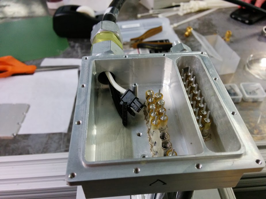
- Feed-through box
- Power/cooling
- Voltage regulator sizing for 32/48 channels
End to End Noise Scan Testing
Attachments (2)
-
IMG_20140122_104148.jpg (97.1 KB) - added by 10 years ago.
HV connector image
-
Feedthru_TDC_Numbering.jpg (230.8 KB) - added by 8 years ago.
TDC numbering on feedthrough board
Download all attachments as: .zip